|
|
|
Helical
Features
|
|
|
Profiles must follow these rules:
- You must sketch a centerline to define the axis of revolution.
- The sketched entities must be a single string of connected
segments
- The string must not cross over the centerline
- The string must never go normal (perpendicular) to the
centerline (i.e. can't loop back)
- If you chose Norm To Traj, the profile entities
must be tangent to each other (C1 continuous).
|
|
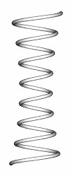
Exercise: CONSTANT
PITCH SPRING
- Start a new part file with default datum planes, and name
it [Spring].
- Choose Feature > Create > Solid > Protrusion
> Advanced > Done, then Helical Swp > Done.
The system displays the feature creation dialog box.
- Review the choices available in the ATTRIBUTES
menu, then Done to accept the defaults. (Constant,
Thru Axis, Right Handed)
- Select a sketching plane that represents the spring's
vertical side view with an appropriate horizontal reference.
- Choose or Accept the Sketching Reference planes.
- Select Centerline and place it vertically on your
vertical reference datum plane to represent the axis of
revolution.
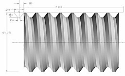
- Sketch a tangent chain of entities, as shown below, to
representing the profile of the surface of revolution.
- Dimension and Regenerate the Profile of Revolution as
shown below.
- When you have finished sketching the profile section,
choose Done.
- Enter a pitch value of [0.12] (the distance from
one coil to the next)
- Pro/ENGINEER places you in Sketcher mode to sketch the
cross-section that will be swept along the trajectory.
- Sketch the cross-section based about the visible cross
hairs per the diagram below. Dimension and regenerate the
cross-section.
- Choose Done.
|
|
| Examples: |
|
|
|
VARIABLE PITCH HELICAL SWEEPS
Helical swept features can also be created with a variable
pitch. In this case, the distance between the coils is controlled
by a pitch graph.
The initial graph is created when you specify the pitch value
at the start and end points. You can then add more control
points to define a complex curve that governs the distance
between the coils along the axis of revolution.
The following options are available in the DEFINE
GRAPH menu:
- The Graph
is only for displaying the pitch data assigned to the Profile
curve.
You cannot select anything from the Graph directly.
- Add Point
- Add a reference point to the graph by selecting a point
in the profile section, or the start or end point. Enter
the desired pitch value at this point. The system locates
the selected control point along the X-axis of the graph
and draws a line with the length equal to the specified
pitch value.
- Remove Point-Remove
a pitch control point by picking it in the profile section.
- Change Point-Change
the value of the pitch at any selected control point, including
the start or end point. Select a point in the profile section
to change its value and enter the new value.
|
|
Exercise: VARIABLE PITCH SPRING
- Start a new part file with default datum planes, and name
it [Spring-variable].
- Choose Feature > Create > Solid > Protrusion
> Advanced > Done, then Helical Swp > Done.
The system displays the feature creation dialog box.
- Define the feature by selecting Variable,
Thru Axis, Right Handed from the ATTRIBUTES menu,
then Done.
- Select a sketching plane that represents the spring's
vertical side view with an appropriate horizontal reference.
- Accept the Sketching Reference planes. (Close)
- Select Centerline and place it vertically on your
vertical reference datum plane to represent the axis of
revolution.
- Sketch a single line, as shown here, to represent the
profile of the surface of revolution.
- Sketch two Points on the line and dimension
them as shown. Then Done.
They will be used as the control points in the pitch graph.
These control points define how the pitch value changes
along the axis of revolution.
To sketch points, choose Sketch > Point, then
select points on the profile geometry and dimension them.
Note: You may put them on the centerline that defines
the axis of revolution if you desire.
- When prompted for the Pitch value at the start
and end of the trajectory, enter [0.10].
|
|
- While the profile section is displayed in the original
window, the system displays a subwindow with the initial
pitch graph in it. Note: The graph window is for
display only, so you can move it to the lower right corner
of your window.
- Choose Define and Add Point from the GRAPH
menu.
- Pick in the main sketcher window on the one of
the additional sketched points that you added to the helical
profile curve and enter [0.200] for the pitch value.
Then add the other point giving it the same pitch value.
- Your graph should look something like this one:
(Note: some of the connecting curves may not show
due to a software issue)
- Once the graph is defined, choose Done from the
DEFINE GRAPH menu.
- You are placed in Sketcher mode again to sketch the cross-section
that will be swept along the trajectory. Sketch,
Dimension, and Regenerate the section. Then
Done
- When you have finished, choose Preview.
- Now redefine the Pitch graph by selecting Pitch
then Define from the Protrusion dialog box. Do a
Change Value of the both the end points, and set
the pitch to [.005] (approximately zero). Done,
Preview and/or OK.
- The resulting feature is shown in the following figure.
|
|
|
|